A mechanical engineering drawing is an engineering drawing that focuses on mechanical components. Mechanical drawings are typically created by using CAD software. Mechanical drawings are used to communicate with suppliers, engineers, service providers, and customers. A drawing set uses the final working drawing, which is detailed with engineering notations, to provide detailed instructions for production. The final working drawing is used to create the machine shop drawing.
Table of Contents
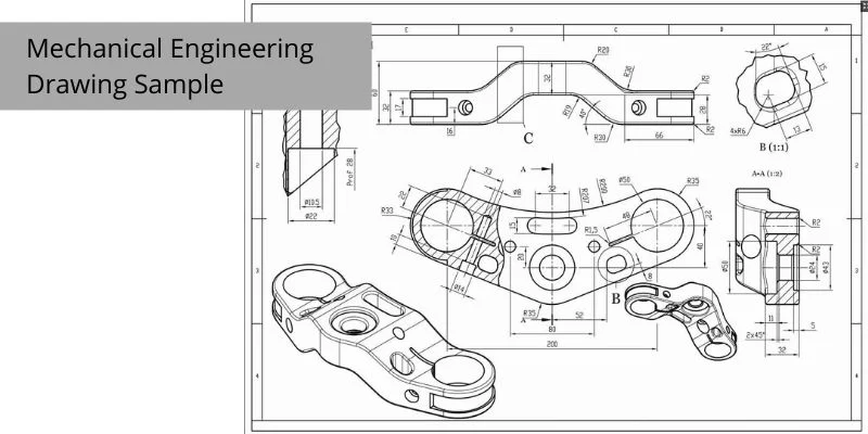
Mechanical Engineering Drawing
A Mechanical Engineering Drawing is a systematic representation of a design or object, illustrating all the technical and physical dimensions, and the required action taken to transform one form to another. It is also called Mechanical Drawing. A Mechanical Engineering Drawing, like most drawings, consists of 2 basic components:
1) The drawing itself and
2) The sizes, names, and quantities of the parts, or scale drawing.
Mechanical Engineering Drawing and its relation with mechanical engineers
Mechanical engineering is a discipline that applies the principles of mechanics to the design and inspection of objects as diverse as vehicles, machinery, and industrial plant equipment. We provide technical drawing services where we cover Mechanical engineering drawing. Mechanical engineering drawing is a technique of mechanical engineering. Mechanical engineering drawing is a technique that simplifies engineering drawings so as to enhance their clarity and conformance to standards. These standards apply to the type and detail of line drawings and to the specific requirements of each industry. It is the task of the mechanical engineer to design and produce drawings made in accordance with provide instructions.
Mechanical Engineering Drawing is the blueprint of your design. The purpose of this drawing is to show people your design. It’s an essential part of the design process and leads to the final product.
How are Mechanical engineering drawings helpful to engineering projects
Mechanical engineering drawings are very important for engineers because they give them a visual representation of what they are designing. Mechanical engineering drawings are the blueprint for the engineering designs that are done. Here you can check our Mechanical Technical Drawing Samples. Mechanical engineering drawings are fundamental for engineering design projects. They are used to convey the technical drawings of equipment, objects, and components.
Four basic components of Mechanical engineering drawings
Mechanical engineering drawings are made up of four basic components: the project sheet, the detail sheet, the profile sheet, and the section sheet. The project sheet is where you’d write down the basic information about the project, the detail sheet includes specifications for different parts of the project, the profile sheet is a representation of how one side of the project looks with all the details, and the section sheet is how the part is broken down with different dimensions.
The Project Sheet
Mechanical engineering drawings are created to show the designer’s ideas to other people who are working on the project. The project sheet explains what the plan is about. The axes are shown on the sheet to show the direction of the drawing. Dimensions are added to the sheet to show the size of the different features on the drawing. Scales are used to estimate distances on the drawing.
The Detail Sheet
Mechanical engineering drawings play a crucial role in conveying the design and detailing of a product. A detail sheet will illustrate every part of the design, as well as any parts that need to be custom-made. The isometric view will illustrate the product as if it were turned on its side. The assembly pictorial view is will illustrate the product as if it is being built, or as an assembly drawing.
A mechanical engineering drawing is a blueprint for a machine or a piece of equipment. These drawings typically show everything from basic blueprints of a building, down to the smallest of details such as an electrical wiring diagram for an engine. Common drawings include detail sheets, shop drawings, and three-dimensional sketches.
The Profile Sheet
The profile sheet can be thought of as one side of the project with all the important details like the dimensions and all the way that it appears. The profile sheet assists workers in manufacturing and assembly. The detailed view shows the front and the back of the object, and assists in making marks on the ground or in the air. This can be seen in the case of steel beams that are being cut in an intricate way in order to create a staircase. To accurately cut the pieces, it is necessary to have an excellent plan of the pieces in advance.
One of the main components of mechanical engineering drawings are the profile sheets. These are representations of one side of the project with all the details.
Also, Read: Technical line drawing and illustrations for your custom needs
The Section Sheet
Mechanical engineering drawings are instrumental to the design process. They allow the designer to develop different scenarios for their design. Understandably, they can be complicated. The section sheet contains the breakdown of the dimensions needed to make the part. The assembly sheet shows how the component is assembled. The detail sheet illustrates the small drawings of the component which can aid in drilling or cutting. Finally, the isometric sheet displays the 2-dimensional view of the part.
Every draftsperson has an innate understanding of space, but the dimensions are more difficult. Mechanical engineering drawings are usually one of the hardest types to get right because they are complex, highly detailed, and often need to be done quickly. A mechanical draftsperson usually has four basic components that they are drawing. The section sheet is where you draw out the external shape of the part, the view of this shape would be seen from one angle, the section sheet is where you break down the part into different dimensions of the part. The layout sheet is where you draw the plan view of the complete assembly, so the full view of the model at the same time.
Submit Your Requirement Here: